The P856 FPGA Design
Block Diagram
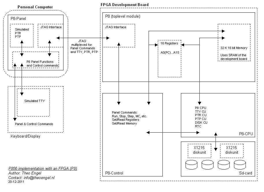
For the design and implementation of this emulated minicomputer, Altera's Cyclone II FPGA Starter Development Board is used. The P856 has a much more extensive and complicated instruction set compared with the Honeywell 316/516, and with that is a typical example of a machine of the seventies. The advantages of RISC were not invented yet, so the instruction decoding is certainly not straightforward. Basicly the P800 machines are 16bit mini's, but many instructions use two 16 bits words, and sometimes even more.
Despite the complex instruction set and the addition of simulated moving head disks by means of the SD-card on the development board, the implementation uses only about a quarter of the logic resources of the FPGA.
The block diagram shows that at top level, the design is split in two main parts:
-
Development Board part: CPU, Peripheral Control Units, Main Memory, Moving Head Disk Units
- Personal Computer part: Panel Functions (Run, Stop, Step, etc.), Peripherals (TTY, PTR, PTP)
The CPU and the peripheral Control Units are implemented into the FPGA, while part of the SRAM chip (64 Kbytes) on the development board is used for the main memory. For the peripherals itself, it was chosen to simulate them on the PC, except for the moving head disks, for which the SD-card on the development board is used. Also all the computer panel functions are simulated on the PC. In order to get information from the simulated peripherals and panel to the CPU and CU's in the FPGA (and the other way around), the JTAG interface is used as a communication link between the development board and the personal computer. The JTAG link is multiplexed for the TTY input and output, the PTR and the PTP and for the Panel functions. Small information packets are exchanged to start, stop or single step the CPU, to set the Sense Switches and to set or read memory locations. These information packets also exchange the peripheral data bytes.
All Panel, peripheral and JTAG communication functions are concentrated in the PC-program P8Panel-xxx.pl, which is written in Perl (ActiveState Perl is being used). For the JTAG-USB interface, use is made of the library/driver of Future Technology Devices International Ltd (ftd2xx.dll, to be loaded in the directory where P8Panel-xx.pl is stored). The Panel program and driver are tested and used at this moment with Windows XP. The control commands that are supported by the Panel program are listed below.
The Development Board / FPGA part of the design is split over six files, written in Verilog:
- P8_xxx.v (Top level, integrating the CPU, Memory, Control, Registers and Disks)
- P8_Cpu_xxx.v (Cpu, Rtc, Peripheral control units)
- P8_Control_xxx.v (Panel functions and communication with the PC)
- sd_cardx.v (Moving Head Disk Drive logic)
- USB_JTAG.v (Altera distributed module for the JTAG interface)
- CLK_LOCK.v (Altera distributed module for the JTAG clock)
The Verilog files can be found in the P8 directory. The USB_JTAG and CLK_LOCK files are Altera/Board specific, and are distributed as part of the Cyclone II development kit. In order to synthesize the design into a workable FPGA configuration file for the Development Board, also a pin declaration file must be supplied. This file binds the FPGA pins to the used interface signals (defined in P8_xxx.v) and is also FPGA/Board specific.
The CPU implements the standard instruction set. To simplify debugging however, the following "features" are added:
- each non-standard or not-existing instruction results in an error state and stops the CPU;
- a Breakpoint Register (BP) is added: when the CPU is running and the content of the Program Counter equals the content of the Breakpoint Register, the CPU stops (the initial value of BP is 0).
In addition, the P8Panel program supports a Trace command. With this command multiple Steps are executed, while after each Step the state of the CPU is displayed.
The whole design takes about 25% of the logical resources of the FPGA (which is a Cyclone II EP2C20F484C7 with 20k Logical Elements), while the design is straightforward without optimization (e.g. each operation where an adder is used has its own adder; not a single ALU to be shared for these operations is implemented). There is of course optimization applied by the synthesis tools at gate level.
The current version of P8 is version 01 (files in the P8-01 directory )
- P856 CPU with 32K 16bit words memory and a Real Time Clock
- supported peripherals: TTY, PTR, PTP and two X1215 disk drives (4 disks)
The Panel Control commands
The Panel program on the PC is started in a command line window with the command:
c:perl P8Panel-xxx.pl.
Because most Panel commands are meant to interact with the programmed FPGA, the FPGA configuration file must be loaded into the FPGA before the Panel program on the PC is started.
The following control commands are supported by the Panel program:
- examine|ex <register> (show register content)
- examine|ex m <address> (interactively shows content of <address>, <address>+1, .. until s is replied)
- deposit|de <register> [<16 bit value>] (if no content, content is requested until s is replied)
- deposit|de m <address> [<16 bit value>] (if no content, content is requested until s is replied)
- mc (master clear; reset the computer to its initial state)
- step|s (execute a single instruction)
- run (execute program, starting with the instruction set in the PC)
- stop|CntrE (stop program execution)
- CntrP (generates a Panel Interrupt)
- state (request-display state of the cpu in the fpga)
- trace [n|>] (executes a single or n instructions showing state (> executes until CntrE)
- ldhex|ldh [s] <fn>.hex (load program into memory from a file (format: absolute hexadecimal))
- load <loadmodule> [<sa>|mon] (load an absolute or relocatable program into memory from a file)
- log [on|off] |
- attach|att ptr|ptp <file> (attach a file on disk to either the papertape reader (PTR) or puncher (PTP))
- detach|det ptr|ptp (the attached file will be detached from the device and the device is closed)
- reset ptr|ptp|mem (resets the PTR or PTP, or sets the memory to zero)
- boot md0|md1|md2|md3 (boot from disk 0, 1, 2, 0r 3)
- dump|du <sa> <ea> (dump memory hex from start address to end address)
- rtc on|off (switches the real time clock on or off)
- exit (disconnect from FPGA and the control program exits; reconnection later is possible by starting P8Panel again)
| means logical OR.
[..] means OPTIONAL argument.
<address> is hex value of 0..FFFF.
<register> is PC|P,A1..A15,BP.
<fn> is a filename.
<loadmodule> is a filename; when its type is:
- .abs, then the file must be in 8+8 absolute papertape format;
- .LM, or lm, or .rel, then the file must be in relocatable disk format;
the program is loaded at address <sa> or at address 0 with the mon option.
When the TTY is used by the CPU, the key combination:
- CntrE stops the execution of the CPU (like the stop command);
- CntrP generates/simulates a Panel Interrupt.;
BP is Breakpoint Register. At the end of the execution of an instruction, BP is compared with PC: the address of the next instruction to execute. In case BP and PC are equal, the CPU is stopped.
When the CPU stops execution (after Run or Step) the state of the CPU is displayed.
Some running examples
In the first example the second moving head disk (MD1) is formatted. The disks MD0 and MD1 have physical device addresses /2 and /22 (drive 0) and the disks MD2 and MD3 have physical device address /12 and /32 (drive 1). The sd-card contains 4 disk images, linked to those device addresses. Disk 0 (MD0, with device address /2) contains the dos5 image from which the system can be booted as is shown in the examples below. Formatting is done with a stand alone format program. The program is loaded with the P8Panel command load. Some detailed explanation between [ and ] in the text below.
F:\FTD2XX>perl P8Panel-020.pl [start the Panel program on the PC; The FPGA is already congigured]
**P8Panel, version 0.020 **P856-022 (32kW)**
Reset USB1
USB1 device was already Closed
Open USB1 device
USB1 device is Open
Init JTAG [USB/JTAG communication link between PC and development board initialized]
> mc [master clear to reset the system]
> load prdk52.lm 1000 [load the relocatable disk format program at address /1000]
Load prdk52.lm
Load 0A4B words; start loading at 1000; relative start address is 082E
LOADING COMPLETE; 1st free address is 2496
Start address (P) is: 182E [start address of the loaded program; it is put in P]
> state
P 182E IR 0000 PSW FC00 H
R 0000 0000 0000 0000 0000 0000 0000 0000 0000 0000 0000 0000 0000 0000 0000
> run [start the disk formatter]
Run, TTY switched to CPU
INITIALISATION OF PRMK52 B05
DISK UNIT PHYSICAL ADDRESS = 22 [MD1]
LABEL = DISK03
DATE = 13-12-11
PACK NBR = 002
SYSTEM USERID = SYSTEM
-WRITING THE IDENTIFIERS
-CHECKING THE IDENTIFIERS
-END OF CHECK
-NBR. OF BAD GRANULES = 0000
RUN AGAIN ? : NO
END OF PRMK52
P 20A4 IR 207F PSW FD00 H [state: the program is ready and stops with a HLT instruction]
R 0000 3030 0030 2020 2020 FFFF 12FA 2020 2020 2020 3032 0005 0000 1826 0000
CPU stopped; TTY switched to Panel
20 ReadSwitches per second; secs:760.984375
>
In the second example the dos5 image on MD0 is copied to the just formatted disk MD1 with label DISK03. The copy is executed with the DOS command SVD (save disk). First DOS is booted from MD0, the the disk is copied. In order to check the result, after the copy DOS is booted from MD1.
> mc [master clear]
> boot md0 [system booted from disk 0]
After IPL is loaded, Boot starts IPL (Default)
Run, TTY switched to CPU
MONITOR ? DOM [ask for DOM]
**DOS 05 **
DATE : 13-12-11
TIME : 14:29
BATCH PROCESSING ? N
USERID: SYSTEM [start a user session on disk 0]
S:SVD /F0,/F1 [save disk0 on disk 1]
S:BYE [stop the session]
USERID: /F1,SYSTEM [check: start a new session on disk 1]
S:LSD [list the system directory]
LABEL = DISK03 DATE = 13-12-11 PACK NBR = 004
*********LIBRARY DIRECTORY*********
****FILENAME****TYPE****ADDRESS****
IPL:DK LM 0010
CCI LM 0200
LEDITF SC 0018
LEDITF LM 0080
DOM LM 01C8
ASM LM 0208
LKE LM 0230
PTRDOM SC 0030
DEB LM 02C0
MAC LM 02D8
PTRDOM LM 0078
TED LM 03B8
BASIC LM 03D0
PREMDK LM 0408
LISDIS LM 0460
M:PROC UF 0488
/OBJCT OB 04C0
OBDIR UF 0640
HSF LM 06D8
FX1 LM 06E0
FX2 LM 0700
F:ERMS UF 0720
FX3 LM 0740
FX4 LM 0758
FX5 LM 0770
FX6 LM 0788
FX7 LM 07A8
S:BYE [looks to be ok; stop session]
USERID:
Keyboard interrupt (Panel: STOP)
P 1BAA IR 5F02 PSW FC40 H E TI
R 1BAA FC40 783E 5459 0000 0000 0082 783E 04E4 FBD6 13C0 4902 7822 801A 022E
CPU stopped; TTY switched to Panel
20 ReadSwitches per second; secs:631.9375
> mc
> boot md1 [boot from the copied disk]
After IPL is loaded, Boot starts IPL (Default)
Run, TTY switched to CPU
MONITOR ? DOM
**DOS 05 **
DATE : 13-12-11
TIME : 14:40
BATCH PROCESSING ? N
USERID: SYSTEM
S:LSD
LABEL = DISK03 DATE = 13-12-11 PACK NBR = 004
*********LIBRARY DIRECTORY*********
****FILENAME****TYPE****ADDRESS****
IPL:DK LM 0010
CCI LM 0200
LEDITF SC 0018
LEDITF LM 0080
DOM LM 01C8
ASM LM 0208
LKE LM 0230
PTRDOM SC 0030
DEB LM 02C0
MAC LM 02D8
PTRDOM LM 0078
TED LM 03B8
BASIC LM 03D0
PREMDK LM 0408
LISDIS LM 0460
M:PROC UF 0488
/OBJCT OB 04C0
OBDIR UF 0640
HSF LM 06D8
FX1 LM 06E0
FX2 LM 0700
F:ERMS UF 0720
FX3 LM 0740
FX4 LM 0758
FX5 LM 0770
FX6 LM 0788
FX7 LM 07A8
S:BYE [also the booting from the copied disk is ok]
USERID:
Keyboard interrupt (Panel: STOP)
P 1BAA IR 5F02 PSW FC40 H E TI
R 1BAA FC40 783E 5459 0000 0000 0082 783E 04E4 FBD6 13C0 4902 7822 801A 022E
CPU stopped; TTY switched to Panel
20 ReadSwitches per second; secs:99.875
>
The third example is the execution of a Fortran compilation, link and run followed by the assembly of a small program. Also that program is linked an executed on the fpga implemented system. A log of the complete program execution is available in this text file.
Use and preparation of the sd-card
The sd-card is used as 2 X1215 diskunits (2*2 disks). A file stored on the sd-card contains the 4 disk images. The filesystem on the sd-card is not used by the fgpa implementation, so the file with the 4 disk images must be stored as a consecuative file on the sd-card. Each disk image in the file is stored at a fixed sector offset in the file: image-0 at sector 1, image-1 at sector 0x2001, image-2 at sector 0x4001 and image-3 at sector 0x6001. Sector 0 is used as a file header and sector 0x7fff is used as a file trailer. The header sector and trailer sector are used to locate where the file is stored on the sd-card. When the Panel program is started, the header sector of the file are searched and when found, it is checked whether the trailer sector is at the expected location. When both sectors are located, the sector address of sector 0 of image-0 (relative sector 1) is stored in the register DO (Disk Offset). Subsequently all accesses to the sd-card are executed relative to the content of the DO register.
F:\FTD2XX>perl P8Panel-021.pl
**P8Panel, version 0.021 **P856-023 (32kW)**
Reset USB1
USB1 device was already Closed
Open USB1 device
USB1 device is Open
Init JTAG
SRMD0.hex loaded [small program loaded/executed by P8Panel to look for the disk images]
Searching for the 1st X1215 disk images on the sd-card.
OFFSET: 0027 C 0001 S 0007
AA00 0000
5038 3030 4649 4C45 4845 4144 4552 2020 FFFF FFFF P800FILEHEADER .... [header found]
Header record at: 0227
Offset set for trailer sector: 8226
Disk Offset: 8226
OFFSET: 0000 C 0000 S 0000
AA00 0000
5038 3030 4649 4C45 5452 4149 4C45 5220 FFFF FFFF P800FILETRAILER .... [trailer found]
Trailer identified: register DO set to: 0228 (X1215 image 0) [register DO set]
> mc
> boot md0 [boot from the sd-card (image-0)]
After IPL is loaded, Boot starts IPL (Default)
Run, TTY switched to CPU
MONITOR ? DOM
**DOS 05 **
DATE : 14-12-11
TIME : 18:31
BATCH PROCESSING ? N
USERID: SYSTEM
S:LSD
LABEL = DISK03 DATE = 13-12-11 PACK NBR = 004
*********LIBRARY DIRECTORY*********
****FILENAME****TYPE****ADDRESS****
IPL:DK LM 0010
CCI LM 0200
LEDITF SC 0018
LEDITF LM 0080
DOM LM 01C8
ASM LM 0208
LKE LM 0230
PTRDOM SC 0030
DEB LM 02C0
MAC LM 02D8
PTRDOM LM 0078
TED LM 03B8
BASIC LM 03D0
PREMDK LM 0408
LISDIS LM 0460
M:PROC UF 0488
/OBJCT OB 04C0
OBDIR UF 0640
HSF LM 06D8
FX1 LM 06E0
FX2 LM 0700
F:ERMS UF 0720
FX3 LM 0740
FX4 LM 0758
FX5 LM 0770
FX6 LM 0788
FX7 LM 07A8
S:BYE [also the booting from the copied disk is ok]
USERID:
Keyboard interrupt (Panel: STOP)
P 1BAA IR 5F02 PSW FC40 H E TI
R 1BAA FC40 783E 5459 0000 0000 0082 783E 04E4 FBD6 13C0 4902 7822 801A 022E
CPU stopped; TTY switched to Panel
20 ReadSwitches per second; secs:99.875
> ex do
DO = 0228
>
The sd-card is accessed in SPI-mode (SPI=Serial Peripheral Interface) by the fpga implementation and the 512 byte sectors are addressed by a sector number. The file with the X1215 disk images must be stored on the card (with a PC) as a consecuative file on the sd-card, which is obtained when the file is stored on a new or fresh formatted card. Maximum supported card size is 2Gb.
The size of the disk sectors on a X1215 disk is 410 bytes. Sectors on sd-cards are 512 bytes. The 410 byte sectors are easily accessed in the simulator by using a direct access method. To simplify the fpga implementation just 512 byte sectors are accessed, so X1215 disk images being used by the fpga implementation are converted to 512 byte sectors. Each 410 byte sector is converted to a 512 byte sector; the last 102 bytes are just filled with slack bytes.
The .sdm file (i.e. the file with the header sector, 4 X1215 disk images and the trailer sector and being stored on the sd-card) is prepared as follows:
1) Convert an X1215 disk image (type .img) with 410 byte sectors into a disk image with 512 byte sectors (type .sdi);
this is done with the utility: p8disk2sdi.pl
2) Store 4 disk images (of the type .sdi) into a file of type .sdm;
this is done with the utility: mk4dsdm.pl
As an example:
STEP 1: [convert a 410-byte-sector disk image into a 512-byte-sector disk image]
F:\p800SDdisk>perl p8disk2sdi.pl dos5.img
Convert P800 X1210/X1215 disk to an SD-card image, version 0.2
Verify moving head disk pack: dos5.img
Verify the sector identifiers.
6528 sector identifiers verified.
The disk image has 6528 sectors
Convert dos5.img to the SD-card image dos5.sdi
6528 sectors copied
0 slack sectors written
SD-card file image ready, 6528 sectors written [dos5.sdi ready]
F:\p800SDdisk>
STEP 2: [move 4 512-byte-sector disk images into a single .sdm file]
F:\p800SDdisk>perl mk4dsdm.pl dos5.sdi emptyX1215pack.sdi emptyX1215pack.sdi emptyX1215pack.sdi
Make a marked SD-card image with 4 P800 disks, version 0.1
The generated image file is: sd4pack.sdm
Header at sector: 0
Copy dos5.sdi to pack0
Image 0 at sector: 1
dos5.sdi copied, 6528 sectors written, fill slack of pack0
1664 slack sectors written for pack0
Copy emptyX1215pack.sdi to pack1
Image 1 at sector: 8193
emptyX1215pack.sdi copied, 6528 sectors written, fill slack of pack1
1664 slack sectors written for pack1
Copy emptyX1215pack.sdi to pack2
Image 2 at sector: 16385
emptyX1215pack.sdi copied, 6528 sectors written, fill slack of pack2
1664 slack sectors written for pack2
Copy emptyX1215pack.sdi to pack3
Image 3 at sector: 24577
emptyX1215pack.sdi copied, 6528 sectors written, fill slack of pack3
1662 slack sectors written for pack2
Trailer at sector: 32767
Four pack SD-card image file sd4pack.sdm ready, 32768 sectors written
Rename the image file in case another one has to be made
F:\p800SDdisk>
The various files for preparing and loading an sd-card can be found in the: SdCardPrep directory